BESS Training Part 1
2024-08-29
Content
-
1. Overview
-
2. BESS Basic Knowledge
-
3. Standard ESS Product
-
4. Type of Power Supply
-
5. Application of BESS
-
6. Project Requirement
1. Overview

|
Feature |
Lead-Acid Battery |
LFP Battery |
Ternary Battery |
|
Trends |
Replacement by LFP |
Popular |
Replacement by LFP |
|
Life Cycle |
500times |
6000times |
1000times |
|
Weight(same capacity density) |
Heavy |
Moderate |
Light |
|
Energy Density |
Low |
Moderate |
High |
|
Charge and Discharge Efficiency |
Low |
high |
high |
|
Safety |
Moderate |
high |
High |
|
Charging Time (Hour) |
Moderate |
High |
Light |
|
Temperature Range (°C) |
’-20-50 |
‘-20-60 |
‘-20-60 |
|
Heavy Metal Indicators |
With lead |
No heavy metals |
With nickel, cobalt, manganese, etc. |
What is BESS?
Energy storage System (ESS) refers to the use of chemical or physical methods to store electrical energy generated from primary energy sources and release it when needed.It including energy and material input and out put, energy conversion and storage equipment.
What is the function of BESS?
The Battery Energy Storage System (BESS) is a system that uses lithium batteriesas energy storage carriers to store electric energy within a certain period of time and supply electric energy within a certain period of time. It has smooth transition, peak shaving, and valley filling. Functions such as frequency modulation and voltage regulation.
What is the Composition of BESS?
The energy storage system mainly consists of energy storage units and monitoring and dispatching management units: the energy storage unit contains energy storage battery packs, battery management system (BMS), Power Conversion System (PCS), etc monitoring and dispatching management units include central control system (MGCC), energy management system (EMS), etc.
BESS Composition
The Operating Progress Introduction

In the energy storage system, the battery pack feeds back the status information to the battery management system BMS, and the BMS shares it with the energy management system (EMS) and the Power Conversion System (PCS); the EMS sends the control information to the PCS and BMS based on optimization and scheduling decisions , control the single cell/battery pack to complete charging and discharging, etc.

Battery management system (BMS): plays a sensing role, mainly responsible for battery monitoring, evaluation The Operating Progress Introduction , protection and balancing; energy management system (EMS): plays a decision-making role, mainly responsible for data collection, network monitoring and energy scheduling; Power Conversion System (PCS): It plays an executive role and its main function is to control the charging and discharging process of the energy storage battery pack and perform AC to DC conversion.
2.BESS Basic Knowledge
Battery System Component
Battery Energy Storage System (BESS)
- Battery Cell: a single battery, the smallest unit of a battery;
- Battery Pack: a series of standard packages for individual batteries;
- Battery Cluster: an energy storage unit composed of a series of battery packs;
- Battery Collection Panel (BCP): between the battery rack and the energy storage inverter, similar to the photovoltaic DC combiner box;
- Power Conversion System (PCS): bidirectional DC AC inverter;
- Battery management system (BMS): Intelligent management and maintenance of each battery unit, preventing overcharge and over-discharge of the battery, extending the service life of the battery, and monitoring the status of the battery.
- Energy management system (EMS)
- Heating, Ventilation and Air Conditioning System (HVAC): Usually used in battery containers to ensure battery ventilation, heat dissipation and warmth;
The Global Battery Manufacturer Market Share

BESS Parameter Introduction
The bess device parameters at 500KW/2MWh:
* KW is the unit of PCS, which refers to the power that a given electrochemical energy storage device can input or output under certain time conditions. The units are W, kW, MW, and GW and the conversion ratio is 1:1000.
* MWh is the unit of battery capacity, which refers to the amount of electricity released by the battery under certain conditions. It is also one of the important performance indicators for measuring battery performance. The units are Wh, kWh, MWh, and GWh, and the conversion ratio is 1:1000.
The Battery Components:
- Battery Cell: a single battery, the smallest unit of a battery;
- Battery Pack: a series of standard packages for individual batteries;
- Battery Cluster: an energy storage unit composed of a series of battery packs;
- Battery Energy Storage Container: Several cluster made of mutiple cluster. For details, pls refer to the the customization specification.

In BESS device, 3S refer to following points:
- PCS (Power Conversion System) also called DC/AC bidirectional converter, which realizes the conversion of electric energy between the power grid and the battery, and monitors and manages the exchange process. It can control the charging and discharging process of the battery, perform AC and DC conversion, and directly supply power to AC loads when there is no power grid.
- BMS (Battery Management System) is a battery management system, which is mainly used for monitoring, calculation, communication and protection of battery packs. It mainly consists of battery management chip, analog front-end, embedded microprocessor, and embedded software.
- EMS (Energy Management System) is an energy management system that can realize real-time monitoring and intelligent management of each equipment in the system. Realize data collection, storage, processing, uploading, operation control, operation strategy formulation, etc., and conduct overall information-based monitoring and management.
Battery Management System including 4 parts:
01 SCU (System Site Control Unit): System site control unit SCU is the highest level control unit of BMS and is responsible for the overall control and monitoring of the entire battery system. It coordinates the work of various subsystems to ensure the safe operation and performance optimization of the battery system.
02 BCU (Battery Cluster Control Unit): battery cluster control unit The BCU is responsible for managing battery cluster (Battery Cluster) level control and monitoring. It monitors and controls multiple battery stacks connected together, coordinating their charge and discharge behavior and status.
03 BSU (Battery Stack Control Unit) can be ignored: Battery stack control unit The BSU is responsible for managing battery stack (Battery Stack) level control and monitoring. It monitors and controls the battery modules inside the stack to ensure their balance and stability.
04 BMU (Battery Module Monitoring Unit): battery module monitoring unit BMU is the lowest level control unit in BMS and is responsible for monitoring and managing the status of individual battery modules. It monitors the voltage, temperature, status and other parameters of the battery module, and transmits this information to higher-level control units for processing and decision-making.
The Reason Why people also called the Battery Management System into 3 parts:
In general discussions, battery management systems (BMS) are often simplified into three main control units because in many applications, the BSU (Battery Stack Control Unit) and BCU (Battery Cluster Control Unit) functions are merged together , or handled by the same control unit. Therefore, some people will merge the BSU and BCU into a unit, called the Battery Cluster Control Unit, thus simplifying the BMS into a three-level structure.
This simplification helps to understand and describe the basic workings of the battery management system, and in general, for most applications, combining the BSU and BCU into a single unit does not affect its performance or functionality. Therefore, although the BMS may actually contain four control units, in general discussions, people usually simplify it to a three-level structure to facilitate understanding and description.
The main function of Battery Management System as below:
- Real-time monitoring of voltage, current, temperature, etc.
- Real-time state of charge SOC estimation
- Various overcharge, over-discharge, over-current, over-voltage, under-voltage, high temperature,low temperature and other abnormal situation alarms and protections
- Establish communication between various parts of BMS and EMS

BMS Interface Diagram
In BESS device, the details introduction for the battery parts:
01 Battery energy refers to the total amount of energy stored in the battery, usually expressed in watt- hours (Wh). Battery energy can be calculated by multiplying the battery capacity and battery operating voltage, that is, energy (Wh) = voltage (V) x battery capacity (Ah). For example, a battery with a battery capacity of 10Ah and an operating voltage of 12V has an energy of 10Ah × 12V = 120Wh.
02 Battery capacity is the amount of charge that the battery can store, usually expressed in units of ampere hours (Ah). The larger the capacity, the more electrical energy the battery can store, that is, battery capacity (Ah) = current (A) x discharge time (h) . Common units of capacity are mAh and Ah=1000mAh. Power banks are generally 5000-10000mAh, and the iPhone 14 battery is 3279mAh.
03 C-rate is used to indicate the battery charge and discharge capacity rate. Charge and discharge rate = charge and discharge current/rated capacity. For example: when a battery with a rated capacity of 100Ah is discharged at 50A, 0.5C. 1C, 0.25C are the battery discharge rate, which is a measure of discharge speed. There are three commonly used ones: if the used capacity is discharged in 2 hours, it is called 0.5C discharge; if the used capacity is discharged in 1 hour, it is called 1C discharge; if the used capacity is discharged in 4 hour, it is called 0.25C discharge. Generally, the capacity of the battery can be detected through different discharge currents. For a 24Ah battery, the 1C discharge current is 24A and the 0.5C discharge current is 12A. The larger the discharge current. The discharge time is also shorter.
04 State of Charge (SOC) indicate the battery's state of charge, or SOC for short. It refers to the ratio of the remaining capacity of the battery after it has been used for a period of time or left unused for a long time and its capacity in the fully charged state. It is usually expressed as a percentage. Simply put, it is the remaining capacity of the battery power.

05 Depth of Discharge (DOD) refers to the percentage of capacity released by the battery to the rated capacity of the battery during battery use. For the same battery, the set DOD depth is inversely proportional to the battery cycle life. When improving performance in one aspect, performance in other aspects will be sacrificed. For example: when DOD is 80%, the cycle life of lithium battery can reach 6,000 ~ 8,000 times.
Note: When the battery capacity is lower than 10%, we will set it to stop working to protect the battery to avoid affecting its battery life.


06 Battery remaining capacity (End of life, EOL), EOL 80% means that the overall battery capacity declines to 80% of the initial capacity after being used for a period of time, corresponding to BOL, Beginning of Life.
07 State of Health(SOH) battery health status (including capacity, power, internal resistance, etc.) is the ratio of the capacity released by the battery from the fully charged state to the cut-off voltage at a certain rate and its corresponding nominal capacity. Generally, when the battery capacity (SOH) drops to about 70% to 80%, it can be considered to have reached EOL (end of battery life). SOH is an indicator that describes the current health status of the battery, while EOL indicates that the battery has reached the end of life. Needs to be replaced. By monitoring the SOH value, the time for the battery to reach EOL can be predicted and corresponding maintenance and management can be performed.
08 Guaranteed power capacity (GPC): the minimum capacity released by the energy storage system within the specified use time.
09 Cycle efficiency (Round-trip Efficiency, RTE): After considering the equipment loss and self-consumption during charging and discharging, the ratio of the total power released by the AC terminal when the battery is fully charged to the power required for the AC terminal to be fully charged.
10 Cycle life: Cycle life refers to the number of times a battery can be charged and discharged(6000 times), usually expressed in the number of cycles. A longer cycle life means a longer battery life.
11 Self-discharge: After the battery is fully charged, its capacitance will naturally decay when it is not in contact with the external circuit and placed at room temperature. Usually, the ambient temperature has a greater impact on it, and excessive temperature will accelerate the battery of self-discharge. The expression method and unit of battery capacity decay (self-discharge rate) is: %/month.
3.Standard ESS Product

3.1 Energy Storage Solution for Residential Scene
3.1.1 AT20kw/50kwh & AT30kw/60kwh Air Cooling ESS Cabinet

Main Features
- Highly integrated
- Storage battery, air cooling device, solar inverter, PCS temperature control and fire protection, and monitoring communication, fully control the system operation status and risks
- Intelligent Management
- Smart BMS system tooptimize the performance
- Intelligent management
- It can realize diversified functions such as system operation monitoring, energy management strategy formulation and remote equipment upgrade


|
Model |
AT20kW/50kWh-2h |
AT30kW/60kWh-2h |
|
Battery Cabinet Data |
||
|
Cell type |
LFP |
LFP |
|
Cell Capacity |
200Ah |
200Ah |
|
System Battery Configuration |
1P80S |
1P96S |
|
Battery Capacity (BOL) at DC side |
51.2kWh |
61.44kWh |
|
System Output Voltage Range |
200-288V |
200-288V |
|
PCS Cabinet Data |
||
|
Rated Output Power |
20kW |
30kW |
|
Max.THD of Curretnt |
<3% |
<3% |
|
Nominal Grid Voltage |
380V, 3L/N/PE |
380V, 3L/N/PE |
|
Nominal Grid Frequency |
50/60Hz |
50/60Hz |
|
System Parameters |
||
|
Dimensions (W * H * D) |
1173*1100*1525mm |
1173*1100*1725mm |
|
Weight |
800KG |
850KG |
|
Life Cycle |
6000times, 0.5C, 80%DoD |
6000times, 0.5C, 80%DoD |
|
Protection Level |
IP55 |
IP55 |
|
Auxiliary Power Supply |
Self-powered/externally powered |
Self-powered/externally powered |
|
Allowable Relative Humidity |
0%~95% |
0%~95% |
|
Operating Temperature |
-10。C~40。C |
-10。C~40。C |
|
Working Altitude |
2000m(derate over 2000m) |
2000m(derate over 2000m) |
|
Cooling Method |
air cooling |
air cooling |
|
Communication Port |
RS485/CAN/APP(WIFI Monitoring) |
RS485/CAN/APP(WIFI Monitoring) |
3.1.2 AT50kw/100kwh Air Cooling ESS Cabinet

Main Features
- Highly integrated
- Storage battery, Integratedenergy, PCS temperature control and fire protection, waterdoor magnetic and monitoring communication, fully control the system operation status and risks
- Flexible parallel
- With the technology of virtual synchronization machine features, it can realize the free machine connection and off-grid switching function of multiple units without communication lines.
- Intelligent management
- It can realize diversified functions such as system operation monitoring, energy management strategy formulation and remote equipment upgrade
|
Model |
AT50kW/101kWh-2h |
|
Battery Cabinet Data |
|
|
Cell type |
LFP |
|
Cell Capacity |
120Ah |
|
System Battery Configuration |
1P264S |
|
Battery Capacity (BOL) at DC side |
101.37kWh |
|
System Output Voltage Range |
844.8V |
|
PCS Cabinet Data |
|
|
Rated Output Power |
50kW |
|
Max.THD of Curretnt |
<3% |
|
Nominal Grid Voltage |
400V, 3P+N+PE |
|
Nominal Grid Frequency |
50Hz |
|
System Parameters |
|
|
Dimensions (W * H * D) |
1200*1000*2150mm |
|
Weight |
800kg |
|
Life Cycle |
6000times,0.5C, 80%DoD |
|
Protection Level |
IP54 |
|
Auxiliary Power Supply |
Grid priority/PV priority/Battery priority (Settable) |
|
Allowable Relative Humidity |
0% - 100% |
|
Operating Temperature |
-25-60。C(derate above 45 。C) |
|
Working Altitude |
3000m(derate over 3000m) |
|
Cooling Method |
air cooling |
|
Communication Port |
RS485/CAN2.0/Ethernet/dry contact |
3.2 Energy Storage Solution for Commercial Scene
3.2.1 AT100kw & AT200kw Air Cooling ESS Cabinet


Main Features
- Highly integrated
- Storage battery, Integratedenergy, PCS temperature control and fire protection, waterdoor magnetic and monitoring communication, fully control the system operation status and risks
- Flexible parallel
- With the technology of virtual synchronization machine features, it can realize the free machine connection and off-grid switching function of multiple units without communication lines.
- Intelligent management
- It can realize diversified functions such as system operation monitoring, energy management strategy formulation and remote equipment upgrade
|
Model |
AT100kW/215kWh-2h |
AT200kW/430kWh-2h |
|
Battery Cabinet Data |
||
|
Cell type |
LFP |
LFP |
|
Cell Capacity |
280Ah(standard Cell) |
280Ah(standard Cell) |
|
System Battery Configuration |
1P240S |
2P240S |
|
Battery Capacity (BOL) at DC sid e |
215.04kWh |
430Kwh(215.04kWh*2) |
|
System Output Voltage Range |
768V |
768V |
|
PCS Cabinet Data |
||
|
Rated Output Power |
100kW |
200kW |
|
Max.THD of Curretnt |
<3% |
<3% |
|
Nominal Grid Voltage |
400V, 3P+N+PE |
400V, 3P+N+PE |
|
Nominal Grid Frequency |
50Hz |
50Hz |
|
System Parameters |
||
|
Dimensions (W * H * D) |
1800*1200*2300mm |
1800*1200*2300mm*2 |
|
Weight |
1680kg |
3360kg |
|
Life Cycle |
6000times,0.5C, 80%DoD |
6000times, 0.5C, 80%DoD |
|
Protection Level |
IP54 |
IP54 |
|
Auxiliary Power Supply |
Grid priority/PV priority/Battery priority (Settable) |
Grid priority/PV priority/Battery priority (Settable) |
|
Allowable Relative Humidity |
0% - 100% |
0%~95% |
|
Operating Temperature |
-25-60。C(derate above 45 。C) |
-25。C~60。C |
|
Working Altitude |
3000m(derate over 3000m) |
3000m(derate over 3000m) |
|
Cooling Method |
air cooling |
air cooling |
|
Communication Port |
RS485/CAN2.0/Ethernet/dry contact |
RS485/CAN2.0/Ethernet / dry contact |
3.2.2 AT115kw/233kwh Liquid Cooling ESS Cabinet


Main Features
- Fast Conversion
- Millisecond level and off-grid switching. If the AC side outage power, it can seamlessly switch to off-grid mode.
- Flexible parallel
- Low voltage is directly connected to the grid, supporting distributed configuration of multiple parallel devices.
- Intelligent management
- Real-time status monitoring and fault recording enable fault warning and fault location.
|
Model |
AT115kW/232kWh-2h |
|
Battery Cabinet Data |
|
|
Cell type |
LFP |
|
Cell Capacity |
280Ah(standard Cell) |
|
System Battery Configuration |
1P260S |
|
Battery Capacity (BOL) at DC side |
232.96kWh |
|
System Output Voltage Range |
728V ~936V |
|
PCS Cabinet Data |
|
|
Rated Output Power |
115kW |
|
Max.THD of Curretnt |
<3% |
|
Nominal Grid Voltage |
400V,3L+N+PE |
|
Nominal Grid Frequency |
50Hz |
|
System Parameters |
|
|
Dimensions (W * H * D) |
1120*1400*2350mm |
|
Weight |
2500kg |
|
Life Cycle |
8000times, 0.5C, 90%DoD |
|
Protection Level |
IP55 |
|
Auxiliary Power Supply |
Grid priority/PV priority/Battery priority (Settable) |
|
Allowable Relative Humidity |
0%~95% |
|
Operating Temperature |
-20-55。C(derate above 45 。C) |
|
Working Altitude |
4000m(derate over 4000m) |
|
Cooling Method |
liquid cooling |
|
Communication Port |
CAN/RS485/Ethernet |
3.3 Energy Storage Solution for Industrial Scene
3.3.1 AT500kw/1075kwh Air Cooling ESS Container
Main Features
- Flexible configuration
- Standardized design, modular assembly, flexible battery capacity configuration
- Highly integrated
- Integrated power conversion system, integrated solution, reducing on-site installation procedures, plug and play, quick website establishment, convenient and efficient
- Temperature protection
- Advanced heat dissipation and temperature control design ensures consistent working temperature and extends service life
- Software parameters
- The echelon protection mechanism combining software and hardware and comprehensive insulation monitoring algorithm ensure system security

|
Model |
AT500kW/1075kWh-2h |
|
Battery Cabinet Data |
|
|
Cell type |
LFP |
|
Cell Capacity |
280Ah(standard Cell) |
|
System Battery Configuration |
5P240S |
|
Battery Capacity (BOL) at DC side |
215kWh X5 |
|
System Output Voltage Range |
648V-864V |
|
PCS Cabinet Data |
|
|
Rated Output Power |
500kW |
|
Max.THD of Curretnt |
<3% |
|
Nominal Grid Voltage |
400V, 3P+N+PE |
|
Nominal Grid Frequency |
50/60Hz |
|
System Parameters |
|
|
Dimensions (W * H * D) |
cabinet size (1200*1200*2150mm)*5,PCS size:1406*650*1976mm |
|
Weight |
10450KG(1900KG*5+950KG) |
|
Life Cycle |
4000times, 0.5C, 80%DoD |
|
Protection Level |
IP54 |
|
Auxiliary Power Supply |
Grid priority/PV priority/Battery priority (Settable) |
|
Allowable Relative Humidity |
5%~95% |
|
Operating Temperature |
-10。C~45。C |
|
Working Altitude |
2000m(derate over 2000m) |
|
Cooling Method |
air cooling |
|
Communication Port |
RS485/CAN/LAN/Enternet |
3.3.2 AT920kw/1863kwh Liquid Cooling ESS Container

Main Features
- Intelligent string architecture design
- Intelligent cluster-level management supports mixed use of new and old battery packs and dynamic capacity expansion.
- Liquid cooling temperature control system
- Three-stage pipeline flow channel, cell temperature difference <3.
- Intelligent operation and maintenance
- Active SOC calibration, no need for walk-in operation and maintenance.
- heptafluoropropane gas fire protection
- Water spray fire protection, and the fire resistance limit of the prefabricated cabin is 2 hours.

|
Model |
AT920kW/1863.68kWh-2h |
|
Battery Cabinet Data |
|
|
Cell type |
LFP |
|
Cell Capacity |
280Ah(standard Cell) |
|
System Battery Configuration |
8P260S |
|
Battery Capacity (BOL) at DC side |
1863.68kWh |
|
System Output Voltage Range |
728V ~936V |
|
PCS Cabinet Data |
|
|
Rated Output Power |
920kW |
|
Max.THD of Curretnt |
<3% |
|
Nominal Grid Voltage |
400V, 3L+N+PE |
|
Nominal Grid Frequency |
50/60Hz |
|
System Parameters |
|
|
Dimensions (W * H * D) |
6058*2438*2896mm |
|
Weight |
25T |
|
Life Cycle |
8000times, 0.5C, 90%DoD |
|
Protection Level |
IP55 |
|
Auxiliary Power Supply |
Grid priority/PV priority/Battery priority (Settable) |
|
Allowable Relative Humidity |
0%~95% |
|
Operating Temperature |
-20。C~55。C |
|
Working Altitude |
4000m(derate over 4000m) |
|
Cooling Method |
liquid cooling |
|
Communication Port |
Ethernet |
3.3.3 AT1.5MW/1.6MWh Air Cooling ESS Container

Main Features
- 1Hour Usage Time(1C cell)
- Customization demand for 1hour usage
- Flexible configuration
- Standardized design, modular assembly, flexible battery capacity configuration
- Highly integrated
- Integrated power conversion system, integrated solution, reducing on-site installation procedures, plug and play, quick website establishment, convenient and efficient
- Temperature protection
- Advanced heat dissipation and temperature control design ensures consistent working temperature and extends service life
- Software parameters
- The echelon protection mechanism combining software and hardware and comprehensive insulation monitoring algorithm ensure system security

|
Model |
AT1.5MW/1.6MWh-1h |
|
Battery Cabinet Data |
|
|
Cell type |
LFP |
|
Cell Capacity |
280Ah(standard Cell) |
|
System Battery Configuration |
8P225S |
|
Battery Capacity (BOL) at DC side |
1612.8kwh |
|
System Output Voltage Range |
650V ~806V |
|
PCS Cabinet Data |
|
|
Rated Output Power |
1.5MW |
|
Max.THD of Curretnt |
<5% |
|
Nominal Grid Voltage |
400V, 3L+N+PE |
|
Nominal Grid Frequency |
50Hz |
|
System Parameters |
|
|
Dimensions (W * H * D) |
10668*2438*2896mm |
|
Weight |
30T |
|
Life Cycle |
6000times, 1C, 80%DoD |
|
Protection Level |
IP54 |
|
Auxiliary Power Supply |
Grid priority/PV priority/Battery priority (Settable) |
|
Allowable Relative Humidity |
5%~95% |
|
Operating Temperature |
-10。C~45。C |
|
Working Altitude |
3000m(derate over 3000m) |
|
Cooling Method |
air cooling |
|
Communication Port |
RS485 Ethernet |
 Innovative Solutions - The European...
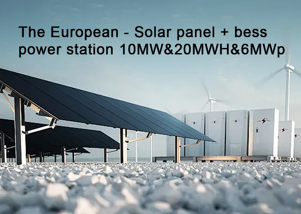
 Innovative Solutions - The European...
 Innovative Solutions - The European...
 Innovative Solutions - The European...
 Key Technologies for Energy Storage Converters or Power Conversion System (PCS)...


