Containerized Energy Storage Power Supply Product Introduction
2024-08-29
1. Containerized Energy Storage System
1.1 Overall Structure And Composition
Seven Parts:
EMS(Energy Manager System)
PCS(Power Conversion system)
BMS(Battery Manager System)
Battery Modules
Fire Fighting Systems
Cooling and heat dissipation system
Video Surveillance System

1.2 20 Ft Container System Products
The specification of this product is 1.25MW/2.45MWh. The energy storage system is configured in a 20-foot container, which integrates the battery system, converter, central control cabinet, temperature control, fire protection, auxiliary system and other components.
1.2.1 1.25MW/2.45MWh (Can be customized upon request)

1.2.2 Main Wiring Diagram for 20-foot Container System

1.2.3 Typical Technical Specifications
|
|
S/N |
Project |
Specification parameters |
|
Battery System |
1 |
System capacity(kWh) |
2451.456kWh |
|
2 |
Rated DC Voltage(V) |
729.6 |
|
|
3 |
Battery System Voltage Range(V) |
615.6-820.8 |
|
|
AC output parameters |
4 |
AC access method |
Three-phase three-wire (without isolation transformer) |
|
5 |
Rated power(kW) |
2*630 |
|
|
6 |
Maximum capacity(kVA) |
2*693 |
|
|
7 |
Rated grid voltage(V) |
400 |
|
|
8 |
Rated current(A) |
2*910 |
|
|
9 |
Maximum operating current(A) |
2*1000 |
|
|
10 |
Rated grid frequency(Hz) |
50 |
|
|
11 |
THDi |
3%(rated rate) |
|
|
12 |
Power factor |
0.99 (ahead)~0.99 (lagging) |
|
|
13 |
Overload capability |
1.1 times long-term |
|
|
Other parameters
|
14 |
Communication method |
Ethernet, CAN 2.0, RS485 |
|
15 |
Protection level |
IP54 |
|
|
16 |
Operating ambient temperature (°C) |
0-45 |
|
|
17 |
Maximum altitude allowed (m) |
<5000 |
|
|
18 |
Fire protection system |
Heptafluoropropane gas fire extinguishing system |
|
|
19 |
Container size L*W*H |
6058*2438*3000mm |
1.3 40 Ft Container System Products
The specification of this product is 1.25MW/4.90MWh, the energy storage system is configured in a 40-foot container, which integrates the battery system, converter, central control cabinet, temperature control, fire protection, auxiliary system and other components.
1.3.1 1MW/2.8MWh(Can be customized upon request)

1.3.2 Main Wiring Diagram for 40-foot Container System

1.3.3 Typical Technical Specifications
|
|
S/N |
project |
Specifications |
|
Battery System |
1 |
System capacity(kWh) |
4902.912kWh |
|
2 |
Rated DC Voltage(V) |
729.6 |
|
|
3 |
Battery System Voltage Range(V) |
615.6-820.8 |
|
|
AC output parameters |
4 |
AC access method |
Three-phase three-wire (without isolation transformer) |
|
5 |
Rated power(kW) |
2*630 |
|
|
6 |
Maximum capacity(kVA) |
2*693 |
|
|
7 |
Rated grid voltage(V) |
400 |
|
|
8 |
Rated current(A) |
2*910 |
|
|
9 |
Maximum operating current(A) |
2*1000 |
|
|
10 |
Rated grid frequency(Hz) |
50 |
|
|
11 |
THDi |
3%(rated rate) |
|
|
12 |
Power factor |
0.99 (ahead)~0.99 (lagging) |
|
|
13 |
Overload capability |
1.1 times long-term |
|
|
Other parameters |
14 |
Communication method |
Ethernet, CAN 2.0, RS485 |
|
15 |
Protection level |
IP54 |
|
|
16 |
Operating ambient temperature (°C) |
0-45 |
|
|
17 |
Maximum altitude allowed (m) |
<5000 |
|
|
18 |
Fire protection system |
Heptafluoropropane gas fire extinguishing system |
|
|
19 |
Container size L*W*H |
14192*2438*3000mm |
2. Key Technologies for Containerized Energy Storage Systems
2.1 BMS
The containerized energy storage BMS is organized in a three-tier management structure:
The first stage is the battery module management unit (BMU)
The second level is the Battery Cluster Management Unit (BCMU).
The third level is the battery accumulation management unit (BAMU).
Tertiary BMS can collect the total voltage, total current, total power of the system, secondary BMS information can be real-time battery system battery SOC, SOH accurate calculation, tertiary BMS should be able to locally store the battery system events and historical key data.

BMS Three Level Architecture Diagram
2.2 PCS
Adopting high-power IGBT as power converter, featuring low noise, high conversion efficiency, low harmonics, high reliability and system stability.
Adoption of industrial frequency transformer isolation technology, so that the DC input and AC output are completely isolated, which improves the safety of the system.
32-bit DSP digital control technology ensures system control speed and accuracy With an isolated network operation mode, in the event of a power outage can still ensure the continuous power supply of a portion of the load, and has the power regulation, harmonic compensation function.
With low-voltage ride-through, anti-islanding protection and other grid protection measures to ensure the safety of grid power supply.

2.3 Battery cell
The advantages of using Lithium Iron Phosphate (LFP) cells for our energy storage system solutions are as follows:Long cycle life and Ultimate safety design.
2.3.1 Long cycle life
Optimize the ratio of positive and negative electrode materials.
Selection of suitable electrolyte.
Strict quality control and production process optimization.
2.3.2 Ultimate safety design
Safe material grade: LFP has stable chemical properties.
Ceramic insulation between the pole and the top cover: to ensure that there is no liquid leakage at the pole, no contact fire between the pole and the top cover, and the temperature at the explosion-proof valve is lower than the fire temperature in the case of internal and external short circuit.
Shell welding process: laser welding of aluminum shell to prevent liquid leakage and isolate water vapor.
2.4 Battery Module
The modules in the battery box are designed with independent air ducts to ensure adequate heat dissipation for each cell.
Module fan supports speed control function to ensure the best operating temperature.
Double protection of module and battery box shell, anti-shock and vibration.
AIoT-based high consistency matching technology ensures the consistency of parameters related to the life of each cell and module, which helps to improve the life of the system
Multi-channel temperature collection inside the module to ensure the safe use of lithium battery modules.
2.5 Thermal Management
Containerized Total Thermal Management Approach
Optimized layout air-cooled heat dissipation based on thermal policy and experimental data
Battery Module In-Module Thermal Management
Modules in the battery box are designed with independent air ducts to ensure adequate heat dissipation for each cell.
Module fan supports speed control function to ensure the best operating temperature.
Under normal operating conditions:
Module temperature difference ≤3℃;Temperature difference of the whole box≤6℃

2.6 Fire Protection System
System program introduction
(Heptafluoropropane centralized fire extinguishing, PACK level detection and protection, firefighting early warning system, water sprinkler firefighting in the box, the actual program can be freely selected according to the demand)
Built-in aerosol fire extinguishing module inside the module, when the temperature inside the module reaches the limiting temperature, the aerosol releases directional protection.
The equipment protection area adopts the full flooding fire extinguishing method, and the cabinet-type Heptafluoropropane fire extinguishing device is used to extinguish the fire automatically, and the system has three starting modes of automatic, manual and mechanical emergency.

2.7 Cloud Platform
The energy storage platform can remotely monitor the data of the system and save it to the cloud storage space. Realize the convenience of no data loss, historical data view, reliability, and reduce the cost of operation and maintenance.

Acquisition function. Collect and manage large-scale, massive device data, persistent storage, distributed storage data, improve data storage security;
Visualization display. According to the characteristics of energy storage system composition, operation mode and other characteristics, specially develop corresponding visualization map, so that the relevant energy storage data are dynamically displayed on the platform interface, so that the scattered data are interrelated with each other, thus effectively perceiving the energy storage operation stat;
At the same time, it provides advanced application algorithms such as basic operational indicators and conventional operational indicators. Some regular application algorithms are built-in, such as consistency evaluation and energy storage operation evaluation. Customized algorithms can also be developed according to the owner's needs;
System encryption and authority management. It has multi-level authority management and system information encryption to meet the privacy requirements.
3. Containerized Energy Storage System Application Scenarios
3.1 AGC Frequency Regulation On The Power Generation Side

3.2 Grid Side Application

3.3 User Side Application

3.4 New Energy Supporting Applications


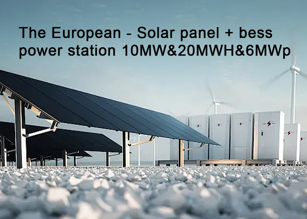
 Innovative Solutions - The European...
 Innovative Solutions - The European...
 Innovative Solutions - The European...
 Innovative Solutions - The European...
 Key Technologies for Energy Storage Converters or Power Conversion System (PCS)...


